
USB Wiring Diagram, Connection, PinOut, Terminals ETechnoG
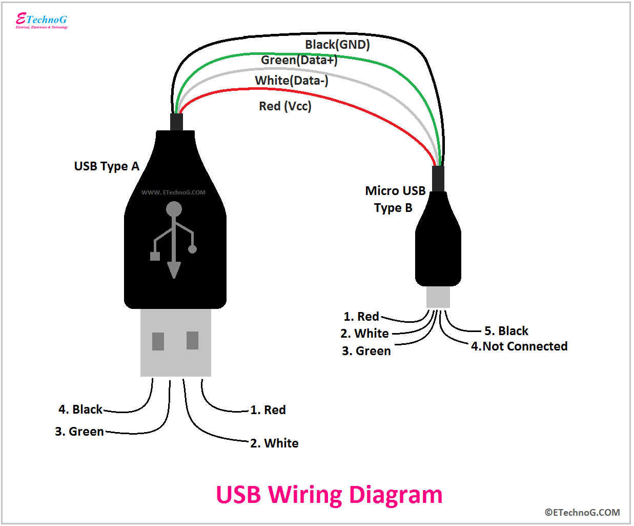
The wiring diagram includes any combination of different types of USB connectors. The most common after USB-type A to USB- type C is "micro USB- type B " to standard " USB-type A " which is generally presents in mobile phone chargers.

Usb C Cable Wiring Diagram
Step 1: Materials and Tools You need: - 2 spare usb cable, or 1 spare usb cable and a type A usb cable plug (I've got mine from two dead mouse) - a multimeter (a continuity tester works fine too) - Soldering equipment (cheap 30W soldering iron works fine) - Electrical tape or heat shrink tubes
USB Wiring Diagram, Connection, PinOut, Terminals ETechnoG
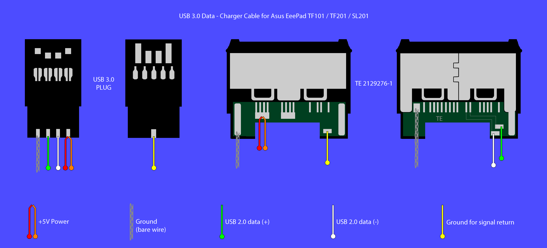
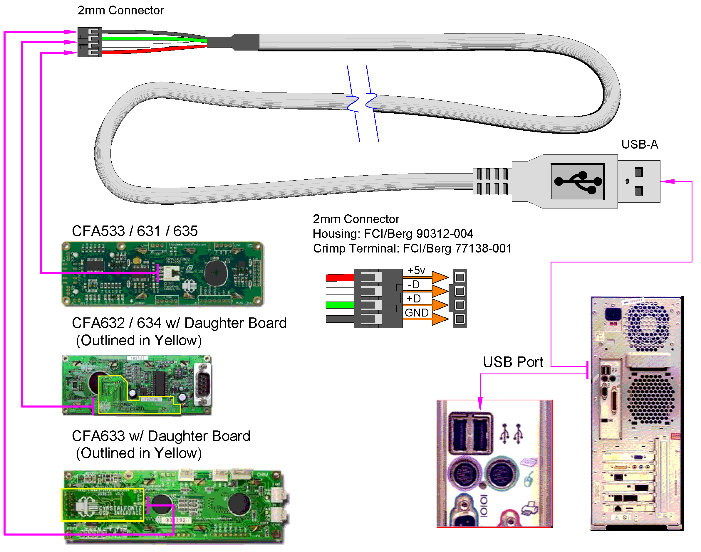
USB 2.0 cable wiring pinout. Very simple. Maximum length of cable is about 5 m for AWG20 and 0.8 m for AWG28 cable. USB D+ and D- are twisted in cable. Outer shell is made of copper braid and aluminum shield. Colors do not mean anything in the wiring scheme. You can use any color wire to rig something.

Micro Usb Cable Wiring Diagram Extension Different Wire Color Data Usb Cable Usb Cable
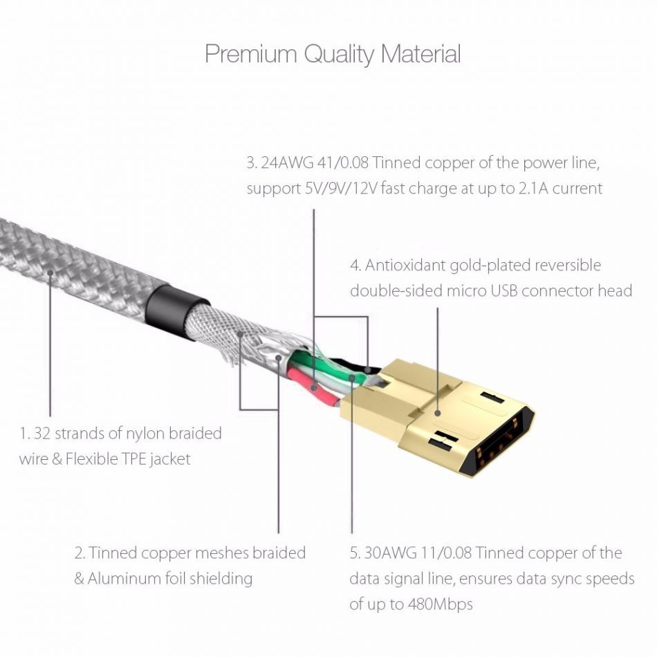
The USB wiring diagram illustrates the physical layout and connections of the wires within a USB cable. It consists of four wires: two power wires (5V and ground) and two data wires (D+ and D-). These wires are responsible for transmitting power and data signals between devices.

Usb Mini B Wiring Diagram
A DIY SATA to USB cable wiring diagram is a self-guided illustration that shows how to connect the wires of a Serial ATA (SATA) cable to a USB cable. The diagram typically includes the color codes and labels of each wire, the connections to be made, and the sequence in which they should be connected. A SATA to USB Adapter is a piece of.
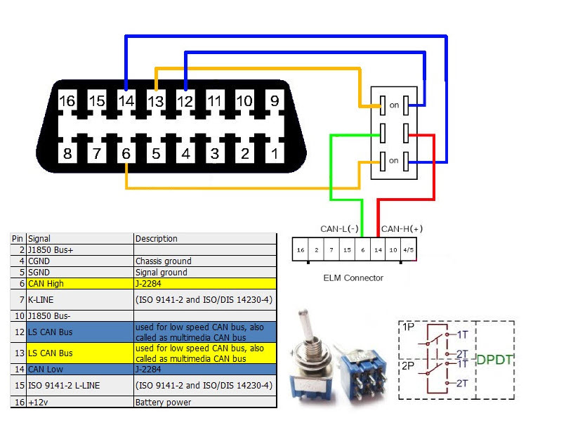
Diy Obd2 To Usb Wiring Diagram Bestsy
What is a USB? The easiest way to connect computer peripherals is through a Universal Serial Bus (USB). The USB is a plug-and-play interface between the PC and the peripherals. The main advantage of USB is that the device can be plugged in or plugged out without the need of restarting the PC
USB Wiring Code Wiring Diagram
Key Takeaways: USB connections on a motherboard consist of two types: USB 2.0 and USB 3.0. USB 2.0 connectors are usually black and have 4 pins, while USB 3.0 connectors are usually blue and have 9 pins. The wiring diagram provides a visual representation of how the pins are connected to the motherboard.
multi usb port circuit diagram Wiring Diagram
A USB 2 wiring diagram is a visual representation of the physical connections required for a successful connection between two USB-compatible devices. It's a graphical representation of a USB cable, showing which pins on the cable should be connected to which pins on the device. The diagram is made up of a series of symbols, each representing.
Micro Usb Wiring Diagram Ecoens
The USB Type C pinout consists of 24 pins, each serving a specific purpose. These pins are organized into four groups: power pins, USB 2.0 data pins, USB 3.1 data pins, and configuration pins. Power Pins: Pins 1 and 4 are used for power delivery. Pin 1 is designated as Vbus, which carries power from the source (e.g., a charger) to the device.

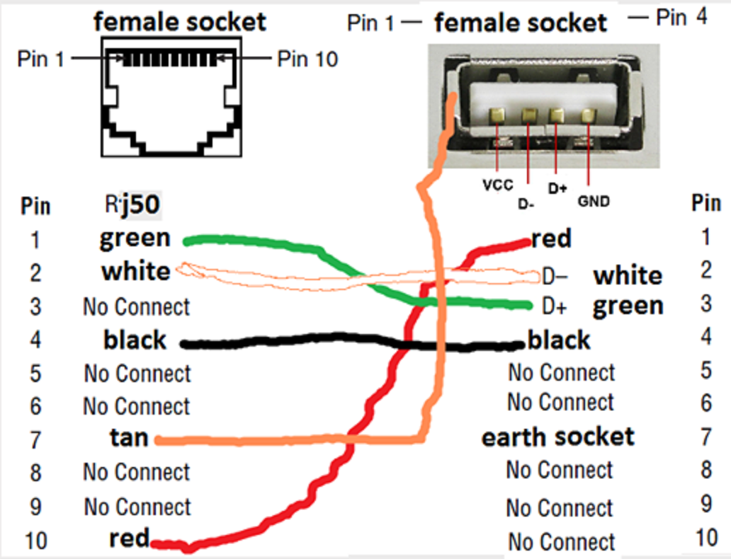
Usb To Female Usb Cable Wiring Diagram USB Wiring Diagram
It contains five pins: two data, two power, and one ground. Cameras, smartphones, and tablets employ Mini-USB and Micro-USB ports. They have a ground pin, two data pins, and two power pins. These connectors are more compact than Type-A and Type-B connectors. USB pinout is crucial for data transfer, charging, and device performance.

7 Pin Usb Wiring Schematic
The basic wiring diagram for a USB plug consists of four different wires, each serving a specific purpose. One wire is responsible for supplying power to the connected device, while another carries the data signals. Additionally, there are two ground wires that help maintain a stable connection and prevent any electrical interference.

Usb Wiring Diagram Wiki
There are four wires inside a cable: red, white, black, and green. This is the most common type of combination. Each of these wires has its own purpose. The >white wire is the positive Data wire. (D+). The green wire is the negative. (D-). Both of these wires are involved in data transfer.

USB Pinout, Wiring and How It Works ElectroSchematics
Both of them have 4 pins. The figure below shows the Pinout of Male and Female versions of both USBs. Note: The Female version is actually the USB connector pinout(Connector of a Keyboard for example) and the male version is the USB port pinout( Ports on your laptop for example) USB type A and B ( Male and Female) pinout
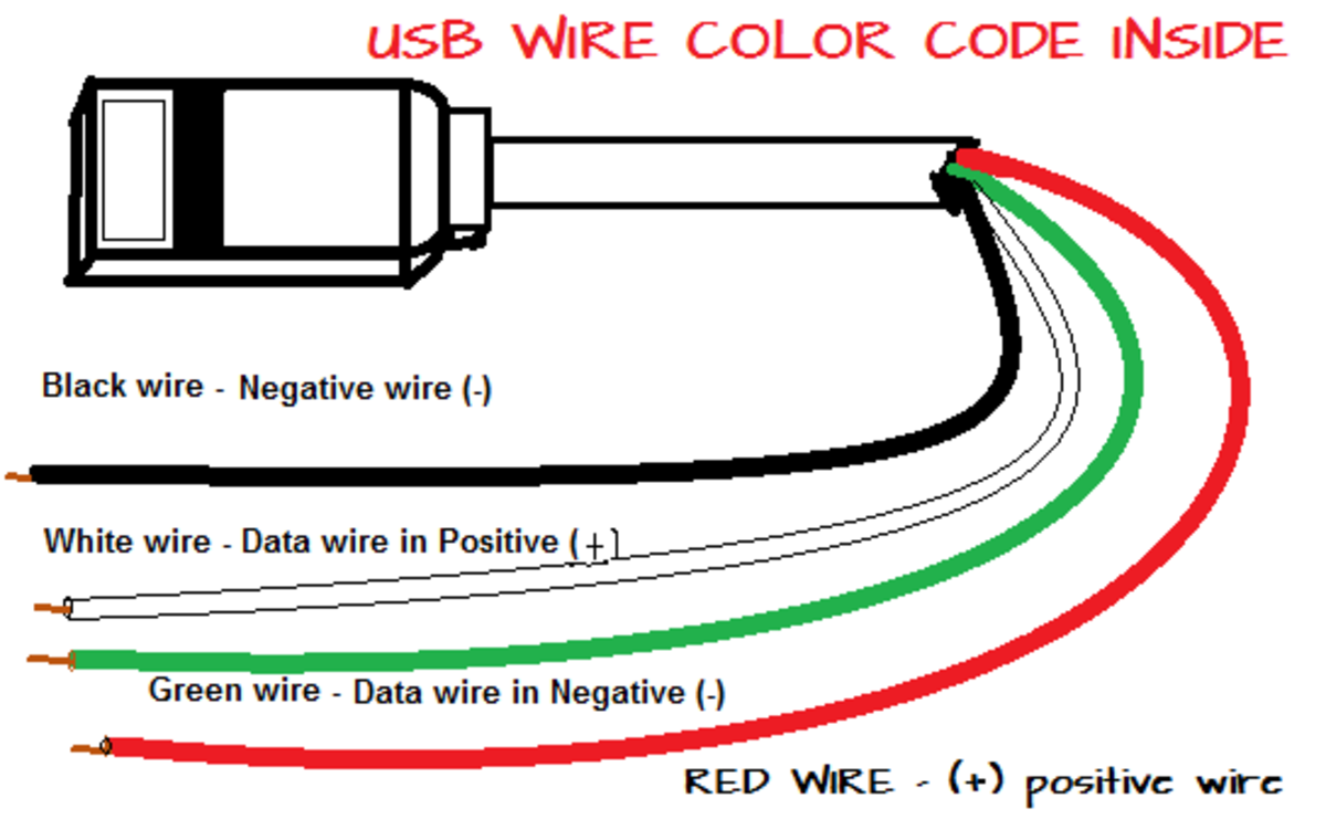
What are the color coding of the four USB wires inside a USB cable or cord
What Each Colored Wire Inside A Usb Cord Means Turbofuture. Usb Pinout Wiring And How It Works Electroschematics. Optec Serial And Usb Communications Cables. Usb Wire Color Code And The Four Wires Inside Wiring Hubpages. Usb C Cable Wiring Diagram P Shine Electronic Tech Ltd. How To Install A Leviton Usb Outlet Blog. Usb On The Go Flash Drives.
micro usb wiring colors Wiring Diagram
15 I make USB cables (USB-A to Mini or Micro primarily), but don't have any experience with USB-C. I would like to create a cable that has a USB-A (2.0) connector on one end, and a USB-C connector on the other (mainly for connecting keyboards to CPUs, and charging devices). How do I wire this properly (typically I use a 4-core 28AGW cable)?

Wiring Diagram Micro Usb
The USB wiring diagram shows four main components: the USB connector, the data wires, the power wires, and the grounding wire. The USB connector is usually a rectangular shape and is divided into multiple pins. These pins are responsible for transmitting data, supplying power, and establishing a ground connection.
